What is the HARPER Project?
HARPER stands for Humanoid Autonomous Robotic Platform for Experimental Research. HARPER was started as a long-term project in the Interdisciplinary Robotics Research Lab (IRRL) and the Cognitive Science Department at Vassar College. The main objective of this project is to create a low-cost 3D printed humanoid robot platform for researchers in behavioral and cognitive science and for hobbyist use.
Initially, the project started with modifying a well-known InMoov Robot11InMoov is an open-source, 3D-printed humanoid robot designed by Gael Langevin. The project publishes printable parts and assembly guides online. You can learn more about them here (link), but past project members quickly identified key problems with the way it was designed: mostly dovetail joints22Dovetail joints slide together and lock without screws. They are fast to assemble, but hard to disassemble and re-tension once parts wear or shift under load. as attachment, lots of worm gears33Under load they generated heat and backlash that make precise control harder. that are inefficient, and control that is not capable of handling substantial load. So, the effort changed to making our own version which will present advantages over the current designs. Multiple people have contributed to multiple efforts in this project, and this has been a long standing learning opportunity for students in Vassar to work in Robotics. I’ve also been part of this project starting from Summer 2025 and have been continuing my work on it. Below, I will lay out some of the things that I have done while working on this project.
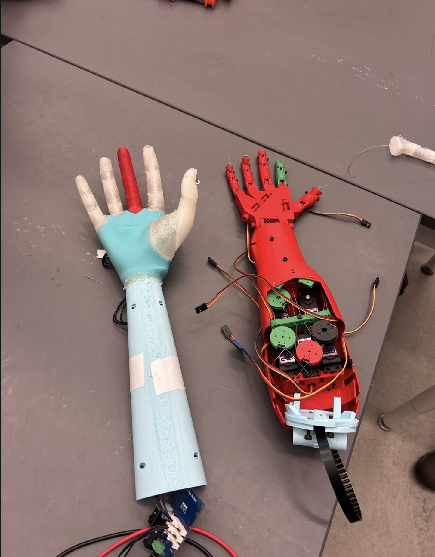
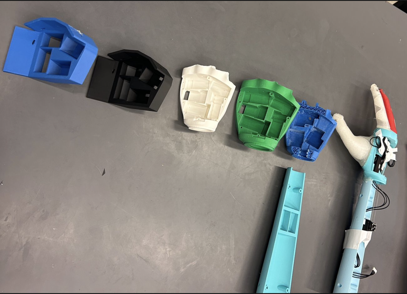
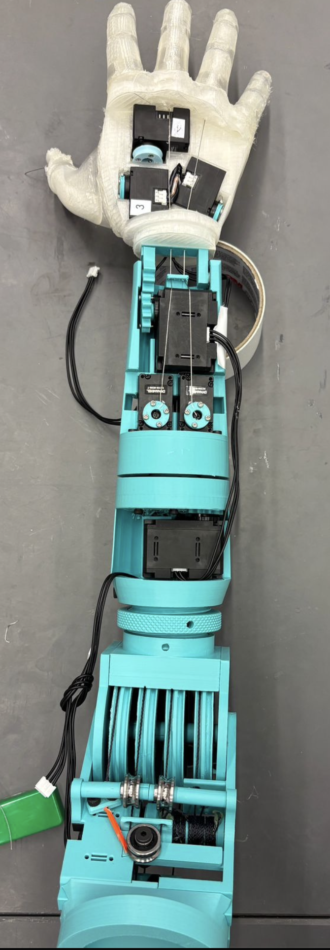
Right: Various design changes that happened when designing the forearm and the hand for the v3 of the arm. This doesn't reflect the current version of the arm.
The arm has gone through several hardware revisions (v2, v3, and beyond) each aimed at stronger joints, simpler assembly, and better control.
Present
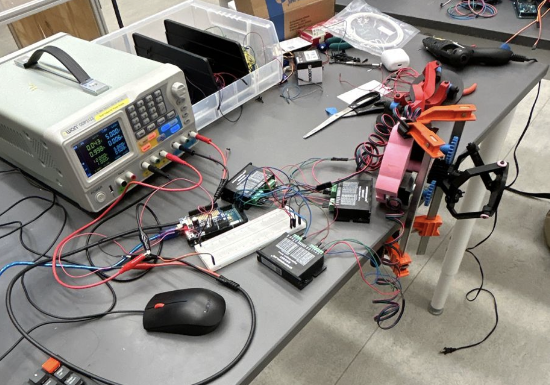
Currently, the main focus of my work has been to test the hardware as robustly as possible. I’ve been working on developing a hardware test platform (github). I’m also working on developing the ROS2 package44ROS 2 (Robot Operating System 2) is middleware for robot software; it has things like topics, services, and drivers that let hardware and algorithms talk to each other. for the arm. Currently, we are finalizing the URDF55A URDF (Unified Robot Description Format) file is an XML model of the robot’s links and joints. of the arm. Significant hardware changes have also happened compared to last summer to make the arm more robust.
The clip is played at 2× speed from the raw hardware test.
Summer 2025
The main work I did was to develop the shoulder module. My end deliverable was a 3 degrees of freedom (DOF)66Degrees of freedom count the independent ways a mechanism can move. In the shoulder, three DOF means the upper arm can orient across three independent rotational axes. serially linked77Serial linkage means each joint connects in a chain: the output of one joint drives the next, rather than a parallel arrangement where several branches meet at a single platform. shoulder module. You can see an image of a final-ish version that I made here:
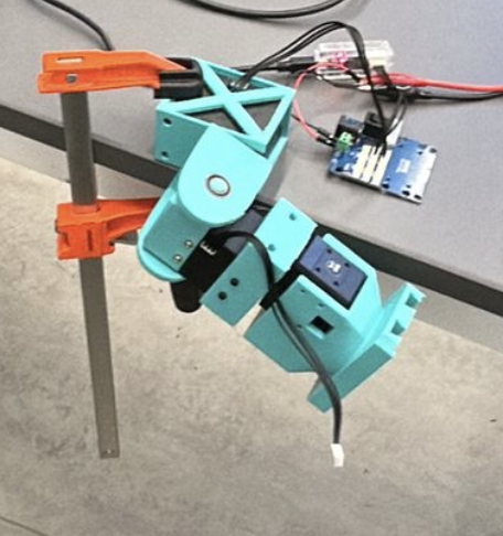
This was the first time I had to learn Fusion360 and 3D design. Before settling into this design, I tried experimenting with spherical parallel manipulators88In a parallel manipulator, several kinematic chains connect the base to one moving platform. Spherical designs aim to produce pure rotational motion at the platform, but the closed loops make forward and inverse kinematics, and control, much harder than a serial chain. and learned a few things about them, especially how incredibly hard they are to control. Specifically, I looked into some spherical 3-RRR mechanism993-RRR means three legs, each with a revolute–revolute–revolute chain of joints, arranged to produce spherical motion at the platform. A revolute joint rotates about a single fixed axis, like a door hinge. (see the figure below).